
Analysis on circuit surge path-the first priority to solve surge issue
Time:2016-11-04 16:11:31 Source: Nums:2961
EMC(electromagnetic compatibility ) technology is a crossover among multiple branches of knowledge. Many may feel it is difficult to solve EMC issue, because electromagnetic field is intangible, untouchable, or even sometimes out of the path hardware engineer intentionally designed on PCB. A string of obscure terms and jargons would make ABC learner or even experienced hardware engineer feel bewildering and forable, such as transformation from electrical field to magnetic field and vice-versa, space radiation, cable transmission, cable radiation, differential mode circuit and common mode voltages.
The most important methodology to analyze EMC issue is highly related to three factors: 1. Electromagneticinterference source, 2.Coupling path, 3.Sensitive source, which consists of the total unity in trinity.
Regarding with surge issue discussed here, interference source is certain in that surge stimulator generates specific type of waveform; coupling path is composed of cable line(major) and space(minor) while sensitive source made by interface chip(major) and sensitive signal(minor). Among all the tests of EMC, the speed rate of surge is, relatively speaking, lower and less high frequency component interference. The waveforms frequently used for test are 1.2/50uS and 10/700uS, both time units keep in uS level. Thus, power discharge pathway should be designed in advance.
The well-designed discharge pathway could be the key to solve coupling path issue, which helps solve EMC trouble.
There are two ways to design surge protection circuit, one is to open up the path and the other one is to block out. Passive components such as GDT, TSS&TVS are usually adopted to construct circuit characterized with low impedance to discharge power to the ground, in particular, putting capacitor in parallel serve the same purpose as well. Electric isolation is also adopted to block out surge by utilizing inductance, resistor and capacitor in series.
Test hardware equipment : security surveillance dome camera;
Port: AC24V (compatible with DC 12V);
Surge magnitude: 1.2/50uS 3KV in differential mode (2Ω),
1.2/50uS 6KV in common mode (12Ω).
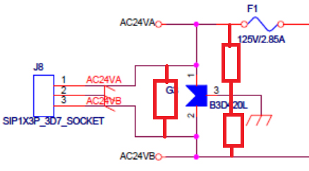
Original protection solution of AC24 port as below:
Analyze and improve:
Checking circuit, you will find out GDT is used for primary surge protection on AC24V port. And post circuit is DC-DC chip instead of Flyback circuit which has much stronger performance of withstand voltage than DC-DC chip. Besides, CM inductance values at 1mH, DM inductance caused by leakage inductance is minor and negligible, hence decoupling effect is very limited. Inevitably, circuit damage happens. The changed impedance value observed by measuring pin of DC-DC chip and the earth, to some extent, validate above analysis.
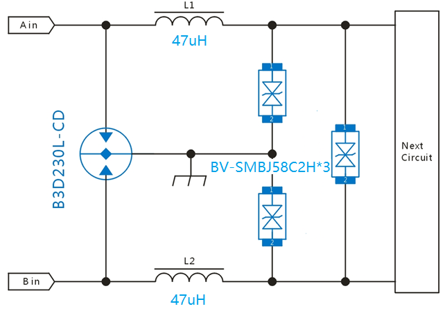
Adding TVS behind CM inductance as secondary protection, TVS P/N could be anyone of BV-SMCJ58CA(1500W),BV-SMDJ58CA(3000W) and BV-5SMDJ58CA(5000W). The ion of component power is related to PTC, CM inductance decoupling.
To change circuit design, due to the space limit of PCB, BVSMBJ58C2H (SMB package, 3000W) is chosen for optimizing solution, it equals to BV-SMDJ58CA. After test on AC24V port, AC24VA passed, but AC24VB failed and equipment damaged due to burned diodes in bridge rectifier.
New problem: After solution optimized, bridge rectifier get burned when AC24VB suffers from surge test. But DC-DC chip works well after switching of rectifier.
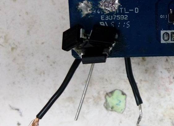
Analyze: To simplify the design of circuit, BV-5SMDJ36CA (5000W) is welded at interface. Please see below picture, three parts serve as CM, DM protection respectively.
The reason to 36V 5KW is to curb residual voltage fallen into the span of withstand voltage of DC-DC chip, but in reality engineer should choose part with voltage more than 40.7V (=24V*1.414*1.2).
Below test is conducted on power PCB ( just PCB itselt, no housing/shell).
Test 1: L-PE 6KV, equipment works well after test;
Test 2: N-PE 6KV, equipment works well after test;
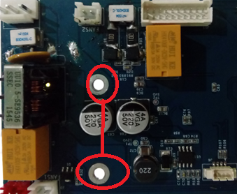
Power PCB works well and no damage found after test1& test2. By looking down into PCB layout, the screw holes are fastened to the whole structure made of metal. And both connect to each other. Using lead wire to connect two screw holes to stimulate ground circuit (below picture, upper screw hole serves as PE ground, lower one serves as digital ground).
Test 3: L-PE 6KV, equipment works well after test;
Test 4: N-PE 6KV,equipment works abnormally after test;
Rectifier bridge gets burned and damaged.
Test 5: N-PE +6KV, equipment works well after test;
Test 6: N-PE -6KV, equipment works abnormally after test;
Rectifier bridge gets burned and damaged.
By analyze the above test results:
1. Test 1, 2,3&4 show voltage value is affected by connection of digital ground and PE ground.
2. Comparison of test 5&6 shows N-PE negative voltage pulse cause diodes damaged.
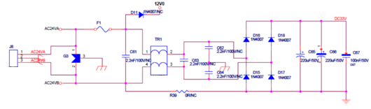
Analyzing surge back-flow pathway:
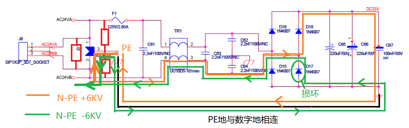
picture in orange, it indicates how N-PE +6KV goes through the circuit. Themajority of power is discharged to ground from AV24VB and a small portion ofpower goes through the capacitor located between D18 and earth.
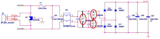
As shown above picture in green, it indicates how N-PE -6KV goes through the circuit. A portion of power goes from PE end to AC24VB end through TVS (AC24VB end loads negative voltage, PE end shows high level); the other portion of power goes from PE end to D17 rectifier by digital ground (PE ground and digital ground connects structurally).
Plus, enhancing current capability of D17 will help pass test. Same result if AC24VB end is series with PTC. These two tests further validate the accuracy of theory analysis.
1. Analysis on surge path is important to surge protection circuit design. A good design of discharging path will enable surge protection to be successful, finding out the root of questions and eliminate them .
2. For AC24V solution, due to the use of DC-DC chip convert, the rectifier bridge’s earth(negative ) has to connect digital ground of secondary circuit. That makes difference from FlyBack circuit. So attention should be paid to protection on the path connecting digital ground and interface .
3. There are many ways to decouple between primary and secondary protection, such as tuning the values of PTC, DM inductance and CM inductance in light of circuit reliability and PCB space requirement.
Firstly DM inductance is recommended, cost stay at average level, less power loss.
Secondly CM inductance is recommended, high cost, big package, TVS behind needs to be high power, but it can help improve performance of EMC.
PTC is the least one to recommend, because its impedance changes as temperature changes, which may bring some power loss. Advantage of PTC: cost is the cheapest, lower than the first two options.
4. As to the ion of the GDT P/N on AC24V port, component with arc voltage higher than 12V is highly recommended. Since the power supply design of AC24V should be compatible with DC12V, which is a common practice in security surveillance industry, so both share the same surge protection solution. The risk of solution lies in GDT applied to DC12V fails to extinguish when circuit current lasts on 12V, otherwise follow-current issue will damage circuit. This point is worth to draw engineers’ attention.
Appendix: AC24V port solution recommended by Bencent